Cobot Payload and Reach Trade-Offs for Assembly Tasks
Payload and reach must be sized together as coupled variables, not picked separately.
Payload and reach are not two line items on a spec sheet to check off independently. For an assembly cell, they are coupled variables that must be sized together, before the purchase order goes out, because neither one can be fixed through programming once the arm is on the floor.
Sizing payload and reach as a system, not as separate specs
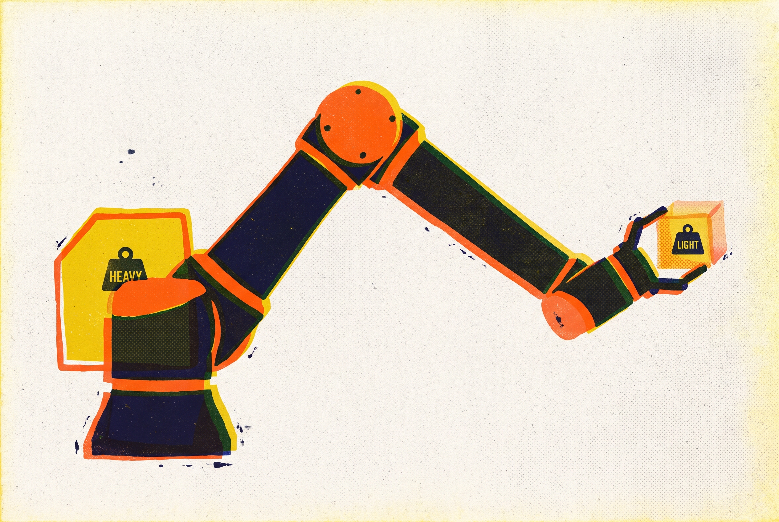
Inside any given cobot family, the same mechanical platform shows up in multiple versions: one with a shorter arm that carries more weight, another with a longer arm that carries less. That trade isn't a marketing choice. A longer arm holding the same mass puts a bigger moment on every joint between the flange and the base, and the manufacturer has only two ways to answer that extra torque: build a heavier, costlier structure to resist it, or cut the rated payload until the joints can handle it safely. The EVST payload selection guide documents this pattern across cobot families, and it holds regardless of brand. Once a buyer understands this, the two specs stop looking like separate numbers to compare against a task sheet and start looking like a single curve that has to clear every point in the job.
The stakes of getting this wrong are not abstract. An arm sized too light for the job will not lift the part with any real safety margin, no matter how carefully the motion program is tuned. An arm with too little reach will not cover the far end of the work envelope no matter where on the table it gets bolted down. Neither failure can be patched with software after the fact; both mean sending the arm back or living with a cell that can't do the job it was bought for. The range of options on the market makes this easy to get wrong: cobot payloads in 2026 span roughly 3 kg to 30 kg, with reach running from about 600 mm to 1,800 mm. That's a wide field to choose from, and a wide field to choose badly from, because the wrong combination of payload class and reach class is simple to pick and almost impossible to correct once the arm is mounted and the cell is built around it.
What the payload number includes (and where the calculation breaks down)
The first place buyers go wrong is treating the payload rating as a number that describes the part alone. The EVST payload selection guide gives the real arithmetic as payload required = part weight + gripper or tool weight + any cabling or sensor mass sitting out at the flange. A gripper with a built-in camera, a multi-finger end-effector, or a bundle of pneumatic lines and sensor cables all add mass that the arm has to carry on every single cycle, not just occasionally. Tooling alone can eat up a third of the total payload budget before the actual part ever gets factored in. A buyer who sizes the arm against part weight has already made a serious miscalculation before the gripper is even selected.
Getting the static total right is only the first checkpoint. A cobot speeding up and slowing down through a cycle needs headroom above that static figure, because acceleration and deceleration both add load beyond the resting weight of the part and tool. The standard guidance is to build in roughly 20 to 30 percent of margin above the worst-case part-plus-tooling weight. That margin isn't padding added out of caution for its own sake. It protects cycle speed, keeps positioning accuracy where the task needs it, extends the service life of the joints, and leaves room to swap in a heavier gripper later without buying a new arm. Running a cobot at its absolute rated limit day after day slows the cycle down and wears the joints out faster than running it with margin in hand.
Then there's a second trap, one that catches buyers who did remember to add in the gripper weight. Payload ratings on most cobots assume a particular center-of-gravity offset from the flange, and a long gripper or an off-center tool shifts that center of gravity farther out, which lowers the usable payload below the number printed on the spec sheet. Two tools of the same weight can produce very different effective payload limits, depending only on how far their mass sits from the mounting flange and in which direction. Every model publishes a payload-versus-center-of-gravity chart for exactly this reason, and checking it against the actual tool geometry, not just the tool weight, is a required step, not an optional one.
Reach, Rated Payload, and Moment-Arm Mechanics
The payload number on a spec sheet is the rating at one specific position, usually close to the base, not a fixed ceiling, and it falls as the tool moves farther out along the arm. The mechanism is the same one that explains why short-reach and long-reach models in a family carry different ratings in the first place: a longer moment arm demands more torque from the joints to hold the same mass steady, so for any given cobot family, the long-reach version is rated for less payload than its short-reach sibling. The EVST payload guide lays this trade-off out directly, and it means the arm has to be sized against the worst-case payload at the farthest point it will actually be asked to reach, not against the single best-case number on the cover of the brochure.
That has a practical consequence that trips up buyers who think in terms of weight alone. A light part that has to be placed far from the base can demand just as much from the arm as a heavy part placed close in. Sizing correctly means plotting the job against the payload-at-reach curve for the specific model under consideration, not against the headline payload figure quoted at the shortest working radius. That curve is a document a buyer has to request from the manufacturer and check against the task, because it doesn't appear as a single number on a standard spec sheet, and a model chosen on headline payload alone can turn out to be unable to carry the required load at the point in the envelope where the job actually needs it. The engineering trade is visible across any manufacturer's product range: a shorter-reach model in a family will out-lift a longer-reach sibling at its own working radius, and that's a deliberate design choice built into the lineup, not a flaw to route around. The most reliable method for working through this is to plot the heaviest part plus tooling together with the farthest placement point the task requires, then select the smallest model whose payload-at-reach curve clears both constraints at once.
Reach extremes carry a precision cost as well as a payload cost. Assembly work typically calls for repeatability of ±0.03 mm or tighter, and cobots on the market in 2026 span a repeatability range from about ±0.02 mm to ±0.1 mm depending on the size of the arm. Repeatability tends to degrade as the arm approaches the edge of its working envelope, so a task that sits right at the limit of an arm's reach is asking that arm to do its least precise work exactly where precision matters most.
An arm sized too light for the job will not lift the part with any real safety margin, no matter how carefully the motion program is tuned.
Sizing reach: covering the full working envelope, not just the farthest pick point
The number printed on the spec sheet for reach describes a radius, and a radius alone doesn't tell a buyer whether the arm can actually do useful work at the edge of it. The failure buyers miss most often is about orientation: an arm can be mechanically capable of positioning its gripper at a far point in the envelope and still be unable to hold the tool at the angle the task requires once it gets there, because the wrist runs out of rotation or the arm hits a joint limit trying to reach that orientation.
A sound sizing method starts with the full task footprint, not just the farthest single point. Lay out every pick point, every place point, every machine door and fixture the arm has to reach around. Find the two points in that footprint that sit farthest apart from a single mounting location, and confirm the arm can reach both of them, at the orientation the task actually requires, without running into a singularity or a joint limit along the way. In practice that usually means leaving real margin inside the nominal reach radius rather than planning the layout right up against it, a point the EVST commissioning guide makes directly.
Sometimes the task footprint is simply larger than any single arm in the catalog can cover from one mounting point. At that stage, a buyer has three ways forward: step up to a longer-reach model, remount the arm on a wall or ceiling to change its working geometry relative to the task, or extend its reach with a mobile base or a linear rail. FANUC's Automate 2026 lineup included a Lincoln Electric Cooper ADAPT welding system built around a CRX-10iA/L mounted on a 7th-axis linear rail, serving two work zones with a rotary positioner, which shows the approach works in practice. A linear rail is a contingency, not a first choice: it adds mechanical complexity, programming overhead, and cost that a correctly sized arm and a correctly planned footprint would have avoided. The rail earns its place when the footprint genuinely exceeds any single arm's envelope, not as a substitute for doing the sizing math correctly up front.
Safety Mode Selection's Effect on Payload and Cycle Time
Safety mode is a sizing input, not a detail to settle after the arm has already been chosen. The speed ceiling that a given safety configuration imposes can mean a correctly sized arm still can't hit the throughput the line needs, and that gap becomes visible at commissioning if nobody accounted for it at selection time.
The clearest evidence of how much this matters: a cobot configured purely for worst-case power-and-force limiting can lose 40 to 60 percent of its potential throughput compared to the same arm running at full speed when the workspace is clear of people, based on observations from assembly-line deployments. Power-and-force limiting, or PFL, lets a cobot work fenceless alongside people. It keeps contact force under biomechanical limits by combining a low moving mass, hard speed limits, rounded geometry on the arm and tooling, and torque-sensing joints that stop on contact, as laid out in the EVST collaborative robot guide. That protection comes at a direct cost to speed, and the cost is large enough to change which model is the right choice for a given takt time.
Two arms rated for identical payload can deliver very different real-world throughput depending entirely on how the cell is configured. A cell that runs in full PFL mode at all times gives up speed constantly, whether or not anyone is actually standing near the arm. A cell using speed-and-separation monitoring instead lets the arm run fast whenever sensors confirm no operator is present, and only slows down when someone enters the zone. The EVST selection guide treats this as a decision that changes the payload-versus-speed math at the point of selection, not a configuration detail to adjust later.
There's a tooling trap hiding inside this calculation too. A heavy gripper mounted on a high-payload cobot can itself push contact force past PFL limits, which forces a gripper redesign before the cell can be certified compliant, even though the arm's own rated payload was never in question. The most common compliance gap is a sharp or heavy end-effector that changes the contact risk in ways the arm's safety system alone cannot fully absorb. ISO 10218-1:2025 and ISO 10218-2:2025, published in February 2025, folded most of the technical specification that used to live in ISO/TS 15066 directly into Part 2 of the standard. The force and pressure limits that govern PFL operation are now addressed as part of the core standard rather than a separate technical specification sitting alongside it. The safety mode gets established during the application's risk assessment, and the resulting speed reduction needs to be built into the throughput estimate before a payload class is locked in, not discovered afterward on the production floor.
A repeatable selection method: four steps from task analysis to arm specification
Reliable arm selection follows a fixed order: start from the task footprint and the total mass at the flange, size payload and reach together against the worst-case combination of both, then check the result against the safety mode and the throughput the line actually needs.
Step one is sizing total payload. Add part weight, gripper or tool weight, and any cabling or sensor mass riding at the flange, then add 20 to 30 percent of dynamic margin on top of that total. The EVST selection guide treats checking the payload-versus-center-of-gravity chart for the specific model under consideration as a required step, to confirm the tool's offset doesn't quietly cut usable capacity below what the job actually needs.
Step two is mapping the full work envelope. Lay out every pick point, process point, and place point the arm has to touch, then find the two points farthest apart from a single fixed mount. Confirm the arm can reach both at the tool orientation the task requires, not merely the position, without hitting a singularity or a joint limit at either extreme.
Step three is crossing the payload-at-reach curve. Choose the smallest model whose curve clears the worst-case payload at the farthest point the task requires, using the curve itself rather than the headline payload figure quoted at the arm's base.
Step four is validating against safety mode and takt. Decide whether the cell will run under full power-and-force limiting at all times or can use speed-and-separation monitoring to run faster when clear, then fold the resulting speed ceiling into the cycle time estimate before the model is finalized. If the safety-rated speed can't meet the line's takt time, the selection has to change at this step, not after the cell is already built.
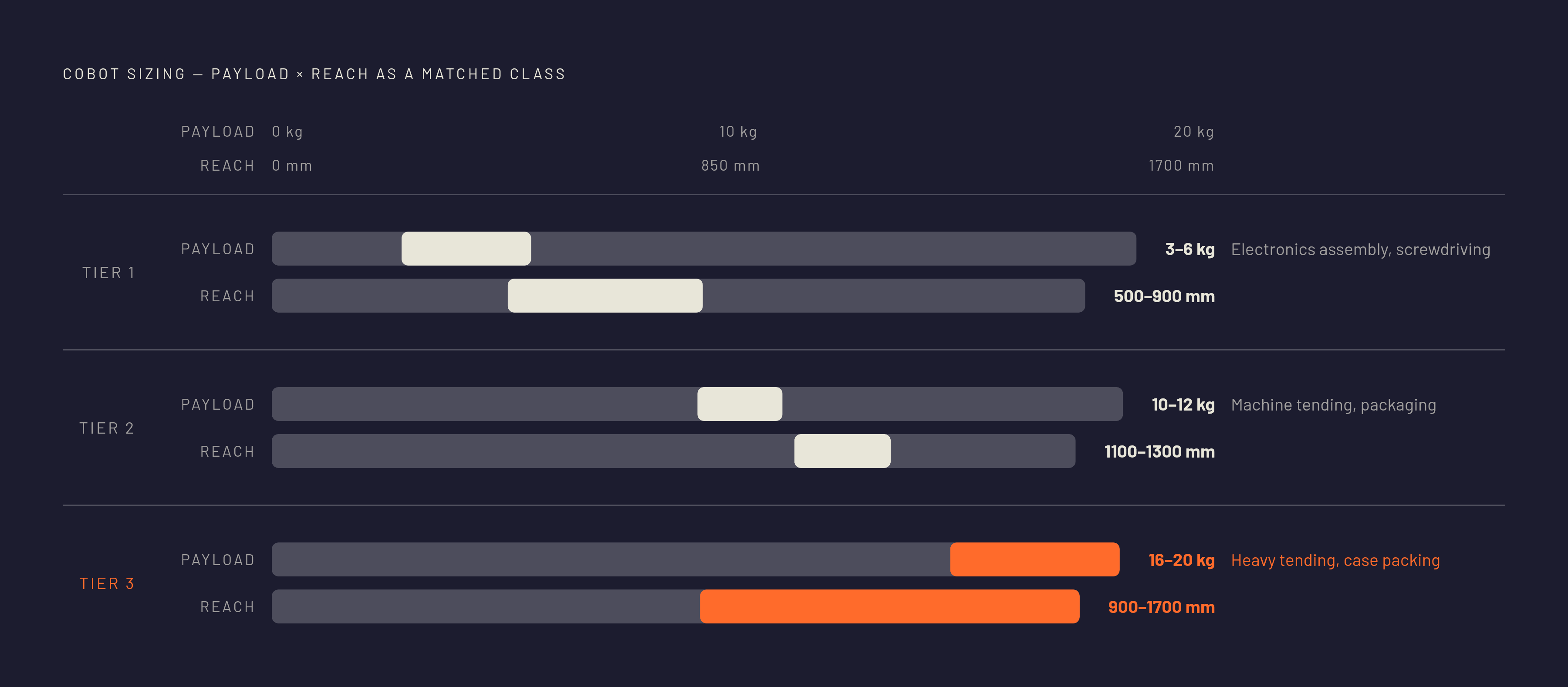
These four steps map onto rough payload and reach classes that cover most assembly work. Electronics assembly and inspection suit arms in the 3 to 6 kg payload range, with 500 to 900 mm of reach, and these arms also handle light pick-and-place and screwdriving. Arms in the 10 to 12 kg range, with 1,100 to 1,300 mm of reach, handle machine tending, packaging, and mid-weight handling. Arms in the 16 to 20 kg range, with reach spanning 900 to 1,700 mm, take on heavier tending, case packing, and multi-part handling.